Arduino Serial Graphics Lcd
Introduction. Welcome to the hookup guide for the Serial Graphic LCD Backpack. In this tutorial, you will learn how to use the backpack to its full potential.

Jan 20, 2016 Como usar Display LCD com Módulo Serial I2c no arduino - Duration: . Sainsmart FULL GRAPHICS 12864 LCD PROBLEM - Duration: .

SparkFun Serial Graphic LCD 128x64. If you mix graphics and text, Hi guys im quite new to all this and am trying to run a serial graphic lcd with my arduino.

LCD displays. EVE Display - FTDI FT80x Embedded Video Engine include touch, display and Audio functions. Provide Arduino reference design and SPI interface.
Arduino LCD playground Sparkfun 128x64 Serial Graphics LCD Library Firmware update required Sparkfun 128x64 Serial Graphics LCD Library. This is an unofficial.
Graphic LCD Hookup Guide; c / Nokia 5100 LCD Example Code Graphics driver and PCD8544 interface code for SparkFun // Type to the Arduino from the serial.
Find great deals on eBay for arduino graphic lcd arduino 20x4 lcd. Shop with confidence.
LCD-09352: This is the serial backpack for graphic LCDs. The SparkFun Graphic LCD Serial Backpack interfaces to either our 160x128 pixel Huge Graphic LCD http.

Video embedded Intro: Arduino powered GLCD Graphic LCD - I made it at TechShop. Displays are always nice. So far I ve just been demonstrating how to use.

Welcome to the hookup guide for the Serial Graphic LCD Backpack. In this tutorial, you will learn how to use the backpack to its full potential. We ll start with the basic hardware overview, then move on to hooking the backpack up to a microcontroller. By the end, you should know all the capabilities of the backpack and how to implement them with any host device.
Before reading this hookup guide, you should be familiar with the following topics in order to get the most out of this tutorial. Please have a look if any of these concepts are unfamiliar to you.
The Serial Graphic LCD backpack was designed to provide a simple, serial interface for large, graphic liquid-crystal displays LCDs. Besides writing text, the backpack allows the user to draw lines, circles and boxes, set or
reset individual pixels, erase specific blocks of the display, and control the backlight. There s also a reverse mode that swaps the colors of the pixels and the background.
Although SparkFun sells the backpack individually, it is also sold with the 128x64 pixel Graphic LCD and the 160x128 pixel Graphic LCD. For the purposes of this tutorial, we will be using both of these LCDs to demonstrate the functionality of the backpack.
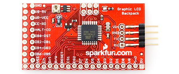
The backpack is controlled with an ATmega168 microcontroller running at 5V/16MHz. This product is primarily intended for embedded applications, but it can easily be connected to a computer and written to with a terminal emulator. Both methods will be covered in this tutorial.
Voltages of up to 7V may be used to power the backpack, however, care should be taken to reduce the backlight duty cycle in such cases to reduce the chance of overloading the voltage regulator on the backpack. To avoid complication with the voltage regulator, it s best to power the backpack at 6V. You can also get away with powering the backpack from another 5V source. Keep in mind that anything below 5V will result in issues with the backlight and/or the display. If you are powering the backpack from a computer USB port or a microcontroller, make sure the output is actually 5V and not something like 4.5V.
Here the contrast potentiometer left and the solder jumper right are highlighted.
There is a small potentiometer on the backpack that allows for contrast adjustments. This should already be adjusted for you, but if text is not readily apparent or otherwise does not suit your needs, feel free to adjust to your liking. If at anytime the text on your LCD becomes unreadable, ALWAYS check the contrast potentiometer first. It is very sensitive, and, if it gets bumped, even just slightly, it can throw off the contrast of the LCD making it unreadable.
There is a solder jumper on the backpack that determines which display is used. When the solder jumper is closed, code for the 128x64 display will run. If the jumper is open, code for the 160x128 display will run. This jumper is soldered during production according to which LCD the backpack is being attached. However, if you wish to use the backpack with your own LCD, you may need to handle this jumper accordingly.
The TX line from the backpack has been left in the final design for future code revisions, debugging and user development, but it is not currently utilized as of this writing.
Let s briefly discuss how these LCDs operate in order to better understand how the firmware we will be using later in this tutorial works. First, let s talk about how the pixels on the LCDs are mapped out.
The graphic LCD is mapped out in Cartesian coordinates as shown in the following picture:
Or, if you are using the 64x128 pixel LCD, it s more like this:
ASCII characters are printed to the screen with
respect to two user-changeable settings, x_offset and
y_offset. These two settings define the top-left corner
bit of a character space, which is 6x8 bits. By
changing x_offset and y_offset, the user can place test
Here is a capital letter B as created in the character space.
Printing characters to the screen happens left to right,
top to bottom, without adjusting x_offset and y_offset.
Further, changing the offsets will change the entire
frame of the text, meaning that writing to the end of
one line and onto the next will happen seamlessly as
the text has no predefined locations where it can or
can t be written except for locations close to the left
and bottom edges of the display.
Backspace is also functional and tries to maintain the
reference frame as set by the user.
The Graphic Serial LCD Backpack is designed to be controlled by a variety of means. One of which is through a serial terminal. This can be useful if you want to use a personal computer as your control device. You can also send commands to the backpack in real time using the ASCII commands. This is useful for testing the LCD before embedding it into a project. Here is a full list of the ASCII commands.
Note: There are several instances where you will need to send ASCII values that require certain, unusual key presses. Anywhere you see, this means that you have to press both the Control key and that character on your keyboard at the same time. If you are using a Mac, some of these commands need to be issued in a slightly different manner. For any command that doesn t work using control, try using the unicode version of that character.
All commands are preceded with , or ASCII
decimal 124 0x7C. This tells the display that a command
sequence follows. Before any of the following
commands are given, they must be preceded with .
The actual character is not and cannot be printed
Sending 0x00 clears the screen of all
written pixels. If you re operating in normal mode, all
pixels are reset. If you re operating in reverse mode,
all pixels are set. An example of a
clear screen command would be to send 0x7C 0x00,
Sending d 0x04 runs demonstration
code. This is in the firmware just as an example of
what the display can do. To see the demonstration,
send 0x7C 0x04, or from a keyboard send and
Sending r 0x12 toggles between white on
blue and blue on white on the 160x128 pixel display and black on green and green on black on the 128x64 pixel display. Setting the
reverse mode causes the screen to immediately clear
with the new background. To set the reverse mode,
send 0x7C 0x12, or from a keyboard send and
r. This setting is saved between power
cycles. If the display is turned off while in reverse
mode, it will next power up in reverse mode.
Sending s 0x13 allows or disallows the
SparkFun logo to be displayed at power up. The
splash screen serves two purposes. One is
to put our mark on the product, but the second is to
allow a short time at power up where the display can
be recovered from errant baud rate changes see
Baud Rate for more info. Disabling the splash screen
suppresses the logo, but the delay remains active. To
disable the splash screen, send 0x7C, 0x13, or from
Sending b 0x02 followed by a number
from 0 to 100 will change the backlight intensity and
therefore current draw. Setting the value to zero
turns the back light off, setting it at 100 or above turns
it full on, and intermediate values set it somewhere in-
between. The number setting in the command
sequence is an 8-bit ASCII value. As an example, to
set the backlight duty cycle to 50, send 0x7C 0x02
0x32, or from a keyboard send , b and 2.
Sending g 0x07 followed by an ASCII
character from 1 to 6 changes the baud rate. The
default baud rate is 115,200bps, but the backpack
can be set to a variety of communication speeds:
As an example, to set the baud rate to 19,200bps,
send 0x7C 0x07 0x33, or from a keyboard send ,
g and 3. The baud rate setting is retained
during power cycling, so if it powers down at
19,200bps, it will next power up with that setting.
In a pinch, the baud rate can be reset to 115,200.
During the one second delay at power up, send the
display any character at 115,200bps.
Sending x 0x18 or y 0x19 followed by a number representing a new reference
coordinate changes the X or Y coordinates. The X
and Y reference coordinates x_offset and y_offset in
the source code are used by the text generator to
place text at specific locations on the screen. As
stated earlier, the coordinates refer to the upper left
most pixel in the character space. If the offsets are
within 6 pixels of the right edge of the screen or 8
pixels of the bottom, the text generator will revert to
the next logical line for text so as to print a whole character and not parts. As an example, to set
x_offset to 80 the middle of the horizontal axis of the 160x128 pixel display send
0x7C 0x18 0x50, or from a keyboard send ,
x and P. Attempting to set values greater
than the length of each axis result in maximizing the
Sending p 0x10 followed by x and y
coordinates and a 0 or 1 to determine setting or
resetting of that pixel. Any pixel on the display can
independently set or reset with this command. As an
example, to set the pixel at 80, 64 send 0x7C 0x10
0x50 0x40 0x01, or from a keyboard send ,
setting a pixel doesn t necessarily mean writing a one
to that location, it means to write the opposite of the
background. So if you re operating in reverse mode,
setting a pixel actually clears the pixel and sets it
apart from the white background. Resetting that pixel
causes it to be white like the background.
Sending l 0x0C followed by two sets of
x, y coordinates defining the line s start and stop,
followed by a 0 or 1 determines whether to draw or
erase the line. As an example, to draw a line from
0,10 to 50,60 send 0x7C 0x0C 0x00 x1 0x0A y1
0x32 x2 0x3C y2 0x01, or from a keyboard send
a. To erase the line and leave surrounding
text and graphics unchanged, submit the same
command but changing the last a to
Sending c 0x03 followed by x and y
coordinates defining the center of the circle, followed
by a number representing the radius of the circle,
erase the circle. As an example, to draw a circle at
center 80, 64 with radius 10 send 0x7C 0x03 0x50
0x40 0x0A 0x01, or from a keyboard send ,
erase the circle and leave surrounding text and
graphics unchanged, submit the same command but
changing the last a to . Circles
can be drawn off-grid, but only those pixels that fall
within the display boundaries will be written.
Sending o 0x0F followed by two sets of
x, y coordinates defining opposite corners of the
box, followed by a 0 or 1 determines whether to draw
or erase the box. This command is exactly like the
draw line command, but instead of drawing a line you
get a box that exactly contains the line between the
given coordinates. As an example, to draw a
rectangular box around the line from 0,10 to 50,60
send 0x7C 0x0F 0x00 x1 0x0A y1 0x32 x2 0x3C
y2 0x01, or from a keyboard send , o,
erase the box and leave surrounding text and
Sending e 0x05 followed by two sets of
x, y coordinates defines opposite corners of the
block to be erased. This is just like the draw box
command, except the contents of the box are erased
to the background color. As an example, to erase a
rectangular block around the line from 0,10 to
50,60 send 0x7C 0x05 0x00 x1 0x0A y1 0x32
x2 0x3C y2, or from a keyboard send ,
Now that we know the commands used to control the LCD, why don t you give it a shot. In this example, you will be using an FTDI Basic to communicate with and control your LCD.
The simplest and fastest way to connect and print to the LCD is to use an FTDI Basic or FTDI Cable. Using jumper wires, connect the FTDI to the LCD like so
Once you have the the LCD wired up correctly, plug the FTDI device into your computer. Open a terminal window. Make sure you have the correct settings: Baud: 115200, 8-N-1-NONE. Once you are connected, begin typing. Everything you type should now show up on the LCD. Refer back to the ASCII Commands section to see which keys you need to press to perform specific commands such as clearing the screen, drawing a circle, or printing text to a specific x,y coordinate.
Talking to the LCD from the computer is fun and all, but the real fun begins when you can print information to the LCD from and embedded device. In the next example, we ll use an Arduino to print information to the LCD.
Before we dive into hooking up the LCD to an Arduino, let s discuss the firmware for a minute. The firmware is the code that resides on the backpack. It serves as a bridge, or translator, between the LCD and whichever microcontroller you use to communicate with it. On top of the firmware, we ve written an Arduino library to make using the backpack even easier.
We ve revamped the firmware that ships with the backpack. It runs smoother than ever to give any project an awesome graphical display. Pending you don t need anything too fancy, you should be able to use the default firmware for all your LCD needs. But that doesn t mean that it s not worth understanding. To see the firmware, head on over to the Serial Graphic LCD Backpack GitHub repository. You can either download the zip file, clone the repo to your computer, or just navigate with GitHub s default editor.
Inside the Firmware folder you ll see a lot of. c and. h files. These are the files that tell the backpack how to interact with the LCD based upon the input received. Since modifying the source code is beyond the scope of this tutorial, we ll leave it here. Just know that if there is some internal functionality that you d like to add, delete, or modify, this is the place to do it.
Do note that you ll need a programmer to change the firmware on the backpack. It is not Arduino compatible, even though the IC on board is an ATmega328, the same IC found on many Arduino boards. Check out the Troubleshooting section for more info on how to reflash the firmware to your backpack.
To make using the Serial Graphic LCD Backpack as easy as possible, we ve written an Arduino library. The library can be found on the GitHub repository. This library basically creates function for each of the commands listed on the previous ASCII commands page. The example sketch that comes with the library demonstrates each function and shows you how to implement them for a full range of purposes on the LCD. If you need a refresher on installing an Arduino Library, please visit our Installing a Library tutorial.
Each function will be listed here and given a short description. However, these functions build upon the commands listed in the ASCII Commands section. For more details on each function, please refer to that section or read the comments provided in the library files.
printStr char Str 78 - Prints a string to the LCD. The buffer is set to 78 by default but can be changed in the header file.
printNum int num - Prints a single number to the LCD.
nextLine - Acts as a newline for text.
These three function exist because the instance of the Software Serial library is declared within the library files to communicate with the backpack. Therefore, using the typical serial.print commands won t work to send text to the LCD while using this library.
clearScreen - Clears the LCD of any and all pixels.
toggleReverseMode - Toggles reverse mode – blue on white for the 160x128 display and green on black for the 128x64 display.
toggleSplash - Turns the SparkFun splash screen on or off. Note that the one second delay on startup remains with or without the splash screen enabled.
setBacklight byte duty - Set the brightness of the backlight. Takes a single int as a parameter. The range is 0-100, where 0 is OFF and 100 is full brightness. Anything higher than 100 will still result in a max value of 100.
setBaud byte baud - Set the baud rate of the backpack. Takes a single int as a parameter with a range of 49-54.
restoreDefaultBaud - Restores the LCD back to the default baud rate of 115200bps.
setX - Sets the x position of where text will appear on the screen.
setY - Sets the y position of where text will appear on the screen.
setHome - Sets poth x and y back to position 0,0.
setPixel byte x, byte y, byte set - Set or reset revert back to the background color any pixel on the LCD.
drawLine byte x1, byte y1, byte x2, byte y2, byte set - Draws a line between two x,y coordinates.
drawBox byte x1, byte y1, byte x2, byte y2, byte set - Draws a box between two x,y coordinates.
drawCircle byte x, byte y, byte rad, byte set - Draws a circle with the center point starting at the given x,y coordinate and then extends out to the given radius.
eraseBlock byte x1, byte y1, byte x2, byte y2 - Erases the block spanning from the two given x,y coordinates.
demo - Initiates an internal demo built into the firwmare.
We ll first go over the quick and easy way to print to the LCD from an Arduino, then we ll go over a more robust method that utilizes the special characters built into the LCD s firmware.
This first example utilizes the built in UART on the Arduino. By doing this, we have to be careful when uploading code to the Arduino while the LCD is connected, since they ll be sharing the same lines. We re going to do things slightly backwards, and upload the code first, then connect the LCD.
With just a few lines of code, you can pass text through the Arduino to a terminal window. Copy this code to a new sketch, and upload it to the Arduino.
This code takes whatever the Arduino receives on its RX line and sends it back out the TX line to the Serial Graphic LCD. You must use Serial.write instead of Serial.print if you wish to see characters on the LCD and not ASCII numbers.
Now, connect the LCD to the Arduino like so..
Make sure your connections are as follows:
You don t need to hook up to the LCD s TX line because you re only sending data to the LCD.
Now, open a terminal window again at 115200, and begin typing. Again text should appear on the LCD. Backspace still works too.
In this last example, we re going to use the Serial Graphic LCD library to do all the work for us. One important feature of the library is that it uses the Software Serial library to create an alternative serial port for the Arduino to communicate to the LCD. The problem with the previous example is that we are using the internal UART and thus have to disconnect the LCD every time we want to upload code. This can be a pain in the butt when you are developing code and need to upload several times.
We can use the previous examples setup for this example, you ll just need to change one jumper wire. Move the jumper wire connected to the Arduino s TX pin to Digital Pin 3 on the Arduino. This is the pin that the Serial Graphic LCD library uses when it initializes the Software Serial library.
Your connections should look like this now:
Or, for the visually inclined, here s a picture of what your connections should look like.
If you haven t done so already, download and install the Arduino library, or clone it to your computer. Head back to the Firmware Details section for more info on installing the library. Once it s installed, open up Arduino, and navigate to the library Example.
Select the proper serial port and board, and upload the example to your Arduino. Once uploading has finished, the library demo should begin. It will run through examples of using almost every function in the library. All that s left is to sit back and enjoy the show.
If you don t see any letters, make sure the contrast potentiometer on the backpack is adjusted accordingly. You ll need a fine-tipped screwdriver to adjust it. Be careful when adjusting this trimpot as turning it too far or too hard can result in the trimpot breaking.
Make sure you are giving the backpack at least 5V. Any lower and you may have an issue with contrast. Some USB ports run around 4.7-4.8V and may not have enough voltage to fully power the LCD and backpack. We recommend powering the LCD with 6-7V.
If you can t see any letters, even when the contrast is adjusted accordingly, then there may be a baud rate issue. If you changed the baud rate and forgot to what you changed it, you can use the restoreDefaultBaud command in the Arduino library to restore the baud rate to its default of 115200bps. Simply create a sketch that imports the Graphic Serial LCD library and then call the restore function in Setup.
Copy and paste this code in to Arduino, make sure the LCD s RX pin is connected to digital pin 3 on the Arduino, and then upload. You should see the screen print Baud restored to 115200.
include //inculde the Serial Graphic LCD library
delay 1200 ;///wait for the one second splash screen
If you are experiencing odd behavior from your backpack, it may be the firmware. If this happens, we recommend updating the backpack with the latest firmware. We ll briefly describe how to do this yourself if you have the proper tools.
The latest version of the firmware can be found on GitHub. Visit the link to the repository. Clone the repository, or download the zip file. Remember the location of this file.
You re going to need some way to upload the firmware to the backpack. We recommend using an Atmel AVR MKII programmer. If you don t have an MKII, you could use something similar such as the Pocket AVR Programmer. Plug your programmer into your computer. You can also use an Arduino board as a programmer. For more info on this and general reflashing firmware information, please see our Installing an Arduino Bootloader tutorial.
In this example, I m going to use Atmel AVR Studio v4.18 to upload the. hex file to the backpack. You can also use AVRDude to accomplish the same task in the command line. If you are running Mac or Linux, you ll either need to look into uploading AVR code on your particular OS, or use a virtual machine such as Wine or VMWare to run AVR Studio in Windows.
Once you ve figured out how to get AVR studio up and running, go ahead and start the program. You should be greeted with a prompt asking you to choose which programmer you re using. Select AVR MKII, or whichever programmer you re using.
Now, you re going to want to select to which chip you plan to upload. Select ATmega168P.
Click on the Program tab. In the Flash section, click the button with three dots on it to browse for the hex file you downloaded from GitHub.
Browse for the. hex file that come with the GitHub download.
Once you have pointed AVR Studio to the hex file, connect the programmer to the ISP header on the backpack, and click Program.
You should see a success message in the bottom of the program. If so, the new firmware should be on the backpack and ready to go.
That about wraps it up. You should now have a good understanding of how the Serial Graphic LCD works and how you can use a variety of means to control the LCD. Now get out there and make some awesome projects with an nice user interface. For more info on the S-G-LCD backpack, check out the links below.